


UH-1D/H/V Fuel System
- Jun 23, 2025
- 13 min read
The UH-1 D, E,H, V fuel system is not a simple system.
In this article I will explain how it works, identify components and how they function in the system. I will also identify problems, fixes, trouble shooting, and ways to keep it working properly. For maintenance and more detailed information use the TM 55-1520-210-23-2 Chapter 10.
Basic Fuel System
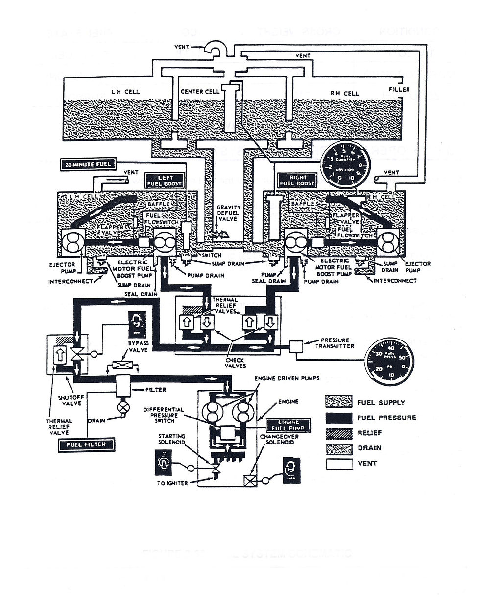
Figure 103

Figure 103 shows the fuel system in its entirety but it is difficult to see individual parts in some areas.
Starting with the fuel filler port on the upper right cell (figure 103 item 22 ). There are a couple of different ways to fuel the aircraft. Basic is open port Open the cap and there is an open port. Second is closed circuit. You open the cap and there is an adaptor in the inlet to connect to the closed circuit fueling hose. When filling the aircraft a float mechanism in the aircraft side will shut off the flow when full. Even though this is beneficial you should monitor this and shut it off manually if necessary.
I have seen aircraft after it doesn’t shutoff nominally. If it does not shut off the only way for the fuel is out is through the vent system with only the 1 inch line exiting the aircraft ( figure 103 item 2 ). In that case fuel was finding every weak point in the system it could find. The pressure practically detached and buckled panels surrounding the fuel cells.
The center cell is next, this is the largest of the cells, then the left cell. The right and left are the two smallest cells. If you look on the engine deck, on the right under the engine oil tank and on the left, below the main fuel filter, there are panels that go to the forward bulkhead. That is the area the right & left cells fit in.
The center cell fits between the inboard walls of two side cells. The center cell goes under the forward firewall to the front edge of the hell hole aft wall. Through the relatively large opening in the back of the center cell (figure 103 item 4) with access through the area under the engine deck. The two outside cells are bolted to the center cell at the bottom of the cells. They are connected by metal flanges with approximately 4 inch openings that are built into the cells near the bottom of the cell, this connects all three aft cells.
Crossover Hoses
Breakaway fittings, in case of a crash, sever enough to pull the hoses away from their connections. The breakaway fittings will then break and seal off both ends keeping fuel in the cells reducing spilled fuel.
One hose, coming from the breakaway fitting on the bottom of the right cell, goes through a breakaway fitting connecting to the aft plate of the lower right cell. From the bottom front of the center cell a hose connects to the lower of the aft crossover hose assembly which connects to both lower cell aft plates.
From another breakaway fitting, a hose from the bottom of center cell, goes to a breakaway fitting (figure 103 item 6) on the bottom of the left cell. Another hose from that fitting goes forward, through a breakaway fitting, to the aft plate on the lower left cell. Notice that there is a forward crossover hose system (figure 103 item 15) and that connect at the front plates of the lower cells where the ejector pumps (figure 103 item 14) are internally mounted allowing fuel to transfer from one cell to another. If the boost pump on one side fails, the ejector pump on the good side can draw fuel from both cells.
Figure 102.
The basics of the fuel system.
The items depicted are placed in relation to where they are in the system, not where they are actually located.
One example is the flapper valves, shown in the middle of the baffle of the lower cells. The flapper valves are at the bottom of the baffle, on the aft side, close to the inside wall of the cell. This places the flapper at the lowest point of the cell. They are positioned there in an attempt to keep fuel on the back side of the baffle, where the boost pump is located, when the fuel level is low.
In cruise flight the nose of the aircraft is low causing the fuel to flow forward away from the boost pump. The output from the boost pump has a T fitting one side to the flow (not pressure) switch (figure103 item11) then to the ejector pump. (figure 103 item 14)
The ejector uses pressure from the boost pump and runs it through a small orifice creating higher velocity causing lower pressure, creating suction picking up fuel from the front of the cell. You will notice there is a hose coming from the ejector pump that carries that fuel to an opening at the top inboard of the baffle and into the back side of the baffle.
This way, in a low fuel nose down condition, fuel is delivered from the ejector pump to behind the baffle to the boost pump. When the hose from the ejector to the baffle is tightened to the ejector pump output and clamped, the hose must be angled up if it has droop in the line otherwise it may not go all the way through the hole thus dumping fuel back into the front of the cell. The other half of the boost pump output goes to the engine out through the plate on the aft of each of the lower cells. From there the hoses connect to hoses that go up the aft wall and connect to hoses that run across the deck, under the tail rotor drive shaft, to the manifold/ shutoff. These two hoses connect to the manifold / main fuel shutoff. Over time these hoses will stretch and push the two hoses they are connected to coming up the aft wall forward.
In this case the vertical hoses can contact the transmission sump case. There should be at least a ½ inch clearance between the hoses and case.
Two problems that show up if this system is not working properly are inaccurate fuel quantity indications and a boost pump light on the caution panel.
The boost pump light is activated by the flow switch (not pressure ) (figure 102 & figure 103 item 11) if the small orifice in the ejector pump (figure 103 item 14 ) is plugged by debris stopping the flow. You may still have normal unobstructed fuel pressure from the boost pump to the engine. Do not pull circuit breakers to find out if this is the case, land the aircraft safely and, while still running , pull the breaker of the opposite (good) pump. If you still have fuel pressure indicated the (bad) pump is still providing fuel to the engine. The fuel pressure you now see on the gauge is the combined pressure of both pumps. This can give you information for your decision making on the safe way to deal with the situation.
Another part of this is if you are below 4,000 ft. above sea level, not ground level, you can pull the breaker in flight. Below SEA level the engine fuel pump (fuel control) can pull fuel from the cells. Above 4,000 ft, atmospheric pressure is not great enough on the fuel in the tanks.
On early aircraft 1966 and earlier the left hand boost pump was bleed air driven. (yes they are still out there ) This pumps usual output is around 20 psi while the right was electrical output around 12 psi., with this system you would see 20 psi on the gage. Today with two cartridge electric pumps output is around 12 psi. People ask if there is something wrong because the gauge is marked 5 to 35 psi. The answer is if it’s in the green it’s good. It’s not the pressure, it’s the volume that you need.
Fuel Quantity
Fuel quantity is another problem. First verify that your fuel quantity system is calibrated properly. (note: the gauge is in pounds not gallons ) The system is a capacitance system which measures the level and density of the fuel. When fueling the aircraft is level, fore & aft, left & right, and it is fueled to the lip of the opening.
On cold days the gauge indicates higher pounds, hot days lower pounds. This is because with cold there is contraction the fuel more dense (heavier) and hot expansion less dense lighter same fuel level.
If you fuel your aircraft when it’s cold, be careful opening the cap in the afternoon. The standard Huey gage is adjustable. There is an adjustment for the low end and one for the high end. The low end is adjusted when all fuel that is drainable has been removed with the aircraft on level ground. Adjust the gage low end to zero. This is the most critical because you need to know when you are running out of fuel. This end of the gauge input is from the two quantity probes in the lower right hand cell, one in front and one behind the baffle as depicted in ( figure 102 & 104 )

This adjustment will not be affected by temperature. These probes are attached to the inside wall of the cell with hose clamps. Use the proper clamps as called out in the Parts Manual. Never use rubber insulator clamps as fuel will cause rubber to fail.
The upper end of the gauge gets its input from the one probe in the center aft cell. ( figure 104 & 103 item 5 ). The probe located in the center cell eliminates the problem of the aircraft not being level left & right.
With the aircraft level and with standard crashworthy fuel cells full to the lip at average temperature, the gage should read 1,400 lbs. Your conditions may vary. If you park your aircraft on a slope right side low when fueling you won’t get as much fuel.
Good cross country trick, park with the left side low & right high and you can get more fuel.
If you have erratic readings of fuel levels or boost pump pressures when fuel is level when you are operating only out of the lower cells, the flapper valve may not be closing like it should and allowing fuel to drain back in to the forward part of the cell. The flapper valve is hinged from the top and flaps aft. When the tank is full, it can allow fuel to flow either way. When the fuel level gets low and the ejector pump is pumping fuel into the aft part of the cell where the boost pump is, he flapper valve must be closed keeping the fuel from going forward.
The hinge for the flapper is attached to the top of the opening in the baffle. The baffle is flexible and sometimes over time gets misshapen and the flapper can’t seal. In that case the flapper may need to be replaced or shimmed.
Before any of this work, fully drain the aircraft. The work can be done without removing the cell by removing the cover on the top front of the cell and the plate with the boost pump and flow switch from the aft bottom. You will have to work through these two openings even if the cell is out. If the cell needs to be replaced you will have to install the flapper valve in the new cell. Instructions are in the manual.
If you notice the upper end fuel quantity readings are erratic, the probe has probably become unclipped from the support brackets. Sometimes the probe has been found floating in the cell. This used to happen when the aircraft was rapidly brought stop. The probe has two plastic sleeves fastened in locations corresponding to the location of the clips. If not clipped on, the plastic sleeves and any metal of the probe touches any other metal the indications will be erratic and may cause damage to the system.
A message came out and is now in the manual, when installing the probe after it is installed in the clips you then zip-tie it around the probe and to the clip bracket. Hint: you cannot do this before installing the assembly. First have the probe electrically connected in the cell. While holding the probe hold the plate with clips and supports installed at an angle to allow you to clip and zip tie the probe in place. Did I mention there is a packing that goes between the plate and the fuel cell?

Twenty Minute light
The so called 20 minute light depicted in (figure 106 & figure 103 item 9) should be called low fuel light. I have had Pilots say when they saw the 20 minute light they started the clock. WHAT power setting / situation are you in?
The 20 minute switch is located in the left fuel cell next to the boost pump. It is a float switch. When the fuel gets low enough it makes contact and turns on the light. The light illuminates between 130 and 240 lbs. If the system is working properly it is very dependable. If you are making right hand orbits and fuel, being a liquid which always finds level , the light will come on early. The quantity shows you have more fuel than that. Quantity probes are in the right cell indicating you have more fuel than you have. Bank left light comes on late, it’s in plenty of fuel. Fuel quantity is low. Level out and the problem goes away.
Aircraft with a rescue hoist on the right side. When hoisting with a lot of weight on right side, getting low on fuel will get a light, yet shows more fuel than you have. Again fuel is level your aircraft is not.
Vent System
The fuel vent system is depicted in ( figure 102 &103 item 17 )
The aft three cells vent from plates on the top center of each cell. To check if you have rollover vent valves, open the fuel filler cap and look to the upper center of the cell. If you see a silver cone shaped thing then you have rollover valve installed. You won’t see the center and right cell vents. When the aircraft were modified by the military MWO 55-1520-210-30-34 all three cells were done. The cells vent above the cone and there is a ball that sits in the bottom of the cone. If the aircraft ends up on its side for some reason, the ball will now run up the side of the cone and plug the vent stopping fuel flowing out the vent. In ( figure 103 item 20 ) the siphon breaker valve is no longer used and the location is capped off.
The two lower cells are vented by vent fittings depicted in figure 103 item 17. There are also breakaway fittings located on each cell. From this point the vent goes through the sidewall of the hell hole, just behind the forward transmission wall, where a flex line is connected. The flex line is then connected to a solid line which goes up side wall then over to the center of the back wall where it connect to the vent from the other lower cell then up over the top of the back wall. It then continues across the deck, under the tail rotor drive shaft, and to the vent manifold. These lines are full of fuel to the level of the fuel in the tanks. Remember liquid finds its own level. These vents allow air into the lower cells.
One aircraft we were working seemed to be drawing more fuel from one lower tank causing a mismatch between the fuel quantity probes on in the right cell and the 20 minute light in the left in level flight. The problem was fixed when we noticed that the flex hose on the right vent drooped between the fitting and the hard line, trapping fuel in the low point, not allowing air in. This caused more fuel to be pumped freely from the left cell. ( early 20 min. light ). The vent system all ties together at the top of the center cell and vents through a 1 one inch hard line exiting near the aft left jack point.
Fuel Drains
There are two fuel drains on each lower fuel cell and one at the main fuel filter as depicted in ( figure 102 & 103 item 13 ) When taking a sample from the main fuel filter you have to have the boost pumps and the main fuel shutoff ON or no fuel will come out. With the pumps on it will come out under pressure. Many times the flex line from the valve to the deck fitting is deteriorated and leaks. People will try to open the valve with the pumps off and nothing comes out because with the main fuel shutoff is closed and no air can get behind the fuel.
Some sump drains you just push up and they drain, you have to pull them down to stop the flow. Some you push up and turn 90 deg. to stay open. To close, turn back 90 deg. pull down and they stop the flow. In some cases the drains will stick open usually because some debris is keeping it from seating. In this case it is good to have a compressor or air charged cylinder available with a hose and rubber tipped nozzle. Put the nozzle into the hole in the drain and push up enough to be sure the drain is fully open and shoot a momentary shot of air and let the valve close. I have done it many times. But if things are broken they are broken.
In taking accurate samples the aircraft should sit still for at least two hours. No fueling, towing or run-ups. If not allowed to sit long enough the water may be suspended in the fuel. Wait, preferably overnight, on level ground. If the aircraft is not level the water maybe in a corner away from the drains.
If you are taking samples use a 30 oz. mayonnaise clear jar, preferably plastic. If you take samples in a small tube you may not get a large enough sample and it will be clear but it’s all water. In using the mayonnaise jar take a sample large enough to fill about a third of the jar. Sample each drain.
Carefully swirl the fuel in jar and centrifugal force will send the water, which is heavier than fuel, to the wall of the jar and collect at the bottom of the jar.
The Navy works in a wet environment. They even transfer fuel from tankers to aircraft carriers in high seas. They have very stringent highly technical equipment to check for water in there incoming fuel which takes a lot of time because the fuel has to sit so the water can settle from suspension. If they are in heavy flight operations and low on existing fuel and need to use newly received fuel, they use the jar method.
Firefighting aircraft with tanks may not be able to get to their drains. In this case any time the tank is off, for any reason, check the drains. Fuel draws water keep your system clean and closed. Most water comes in with the fuel. Check the packing on your fuel cap and adjust as necessary the tension on the latch.
I have many times seen after fueling the aircraft hoses put away, trucks driven away and fuel caps are hanging from an open port. It’s not only water it’s also dirt that is of concern. . Heli- bases are not a clean environment. I have, in the morning, found caps hanging from an open port overnight. End of day everyone is tired last thing to do is fuel the aircraft. They will take the hose out and walk or drive away with the cap not installed.
Don’t forget to also take samples from your truck or storage tanks.
Hope this helps, Pete Frinchaboy


Comments