


Using the TM 55-1520-210-23P manuals
- May 20, 2024
- 3 min read
To assist those who were not military and taught how to read the TM Manuals for UH-1 Maintenance.
On the text pages that go with the diagrams the individual parts are listed. There are 10 Column’s. First is the figure number. Column 2 is the item number. Column 3 is the Code. Column 4 is the NSN Federal stock number. Column 5 is the manufacturers code ( 97499 ) is Bell. Column 6 is the part number. Column 7 is a description of the item or assembly. Column 8 shows the aircraft models that the item / items can be installed on. Column 9 shows unit of issue. Column 10 tells you the number of these items that are necessary to complete the whole assembly. Codes Column 3. The only codes that will transfer to the civilian world are the ones that start with ( M ). If the first letter is M it means Manufacture the item following letter is what level of maintenance is allowed to manufacture the item. In the civilian world it’s who has the equipment and training.

In door 1 find the slider.

In door 2 the slider is item 26 you will notice there is an item 26A in Column 3 under code for item 26A starts with M. You will notice there is no ( NSN ) Federal stock number but there is a part number. You now take this part number and go to the TM 55-1520-210-23-3 Maintenance Manual Appendix D. There are a couple of lists of part numbers in appendix D, keep looking until you find the list with that part number. It will then tell you which drawing to go to which will give you the necessary information to manufacture the item. Item 26A happens to be on the last page of appendix D. You will have to take the snap ring and bearing from the slider, if they are serviceable to install in the roller. Sometimes there is a Federal stock number and there is a code in Column 3 of (M ) this means you will still have to manufacture the part.
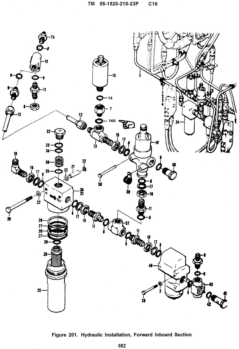
In Hyd filter 1 find the filter assembly.

You will notice there are a number of items depicted in this area. You will need to look in Column 7 to come up with the right combination of items to keep the filter from leaking. There is information on this in the maintenance manual in the area that tells you how to do the job. The filter is the same for all. You must find the part number of the filter head, this will tell you which combination of bowl, packing and backup rings are necessary for your filter assembly. You will notice that two of the filters assemblies use the same packing and backup rings. Now look at Column 10 to find out how many are needed. You will notice of the two assemblies that use the same packing and backup rings one uses 1 backup ring and one uses 2. Having worked with a fleet of eleven Huey’s all but one had the same filter assembly. The other was the one that only used a single packing no backup rings. This caused numerous trips to the field for filter assemblies seeping and each time the mechanics took the same packing and two backup rings that were used in all the other aircraft. The problem was finely fixed when we changed the filter assembly to the same part number as all the rest.

In Seat 1 there are a number of items necessary to complete everything depicted.

Now go to Seat 2 Column 7. At the top of the page you will notice that the first item listed has no dots in front of it. The item just below it has one dot. The next item seat bottom has two dots. That’s the one that has two dots is a subassembly of the one dot. The next item is screw tapping with three dots. Items required 12. The next item is Stanchion assembly back to one dot followed by numerous items of two dots which make the stanchion followed by one doters which are individual items. If you order a one dot item you will get all the 1,2,3,4 dot items that follow. If you only need to replace a 2,3,4 dot item only order that item not the whole assembly.
If you have any questions regarding manuals or comments on this article feel free to contact me 916-837-9437 Cell
Pete Originally posted 4/16/2019


Comments